
Use Two C4 Model Diagrams, Not Four, for Software Teams

The C4 model gives you four levels of software architecture diagrams: system context, container, component, and code, created by Simon Brown as a lightweight alternative to heavyweight notation. Most teams only need the first two. Start with a system context diagram to set scope, add a container diagram to show the moving parts, and reach for component or code diagrams only when a specific decision genuinely requires that level of detail.
TL;DR:
- Most teams only need to focus on system context and container diagrams, which are sufficient for understanding and communication during development.
- Creating and maintaining component and code diagrams should be reserved for cases with significant internal complexity or specific detailed needs.
- Link diagrams to architectural decisions and review updates regularly to prevent them from becoming outdated or confusing.
- Diagram-as-code tools like PlantUML offer better version control for frequently changing architectures, while GUI editors suit quicker initial drafts or non-technical collaborators.
- Prioritizing current, simple diagrams over comprehensive but outdated ones provides clearer understanding and fewer maintenance headaches.
Table of Contents
- What Is the C4 Model and What Do Its Four Levels Show?
- Which C4 Diagram Fits Which Audience?
- How Do You Create C4 Diagrams Step by Step?
- What Separates a Good C4 Diagram From a Confusing One?
- What Tools Work Best for Creating C4 Diagrams?
- Why Do C4 Diagrams Go Stale, and How Do You Stop It?
- How Does C4 Compare to UML and ArchiMate?
- How Do You Keep C4 Diagrams Accurate as Architecture Changes?
- The tradeoff between precision and speed in agile teams
- Keep Your Architecture Docs as Current as Your Code
- Sources
- FAQ
What Is the C4 Model and What Do Its Four Levels Show?
Think of C4 the way you think of Google Maps. You do not zoom straight to street view when someone asks where your city is. You start at the world map, then the country, then the neighborhood, then the building. The C4 model applies that same zoom logic to software architecture, and it is notation and tool independent, meaning you can sketch it on a whiteboard or generate it from code without breaking the framework’s rules.
Each level answers a different question:
- Level 1, System Context: shows your system as a single box, surrounded by the users and external systems it talks to. No internal detail, just boundaries and relationships.
- Level 2, Container: zooms into that box and shows the applications, services, and data stores that make it run, along with the technology each one uses.
- Level 3, Component: zooms into a single container and shows the major structural building blocks inside it. Use this selectively, not for every container.
- Level 4, Code: shows classes, interfaces, or functions. This is optional, and most teams pull it straight from an IDE or a UML export rather than drawing it by hand.
The framework also supports secondary diagrams for system landscape, deployment, and dynamic behavior, but those four levels are the backbone of C4 model architecture.
Which C4 Diagram Fits Which Audience?
Each level of C4 model visualizations was built for a different reader, and matching the diagram to that reader is what makes the model useful instead of decorative.
- System context diagrams serve almost everyone. A product manager, an executive, a new hire, and a security auditor can all read a context diagram without technical background, because it uses plain boxes and arrows to show what talks to what.
- Container diagrams serve architects and developers making structural decisions. This is the diagram you pull up during a deployment planning meeting or a technology selection debate, because it shows the actual applications, APIs, and databases involved.
- Component diagrams serve the developers who own a specific container. They matter during a design review for a complex service, but they go stale fast if nobody maintains them, so reserve them for containers where the internal structure is genuinely hard to hold in your head.
- Code diagrams serve implementers working through a tricky class hierarchy. Most teams skip drawing these by hand entirely and generate them from source when needed.
System context and container diagrams are sufficient for most development teams; component and code diagrams should be the exception, not the default. If you are onboarding a new engineer or briefing a stakeholder, context and container cover it.
How Do You Create C4 Diagrams Step by Step?
Building C4 model diagrams for a real system is less about drawing tools and more about sequencing. Skip a step and you end up with a component diagram that contradicts a container diagram nobody updated.
- Sketch the system context first. Define the boundary of your system, name the people who use it, and name every external system it depends on. This step alone often surfaces disagreements about scope that would otherwise surface much later.
- Build the container diagram next. List every application, service, and data store, and note the technology choice for each one. This becomes the diagram your team actually references week to week.
- Add component diagrams only where they earn their keep. If a container’s internals are genuinely complex, or a new developer keeps asking the same questions about it, draw the components. Otherwise, don’t.
- Generate Level 4 from code when you need it. Use an IDE plugin or reverse-engineering tool rather than hand-drawing class diagrams, since automating this level keeps it accurate without manual upkeep.
- Put diagram sources under version control and set a review cadence tied to your change process, not a calendar reminder six months out.
Pro Tip: Attach each container or component diagram to the design decision that produced it. A diagram floating with no context is the fastest way to end up with three conflicting versions in three different decks.
What Separates a Good C4 Diagram From a Confusing One?
The difference between a C4 diagram that gets referenced for a year and one that gets abandoned after a sprint usually comes down to discipline, not drawing skill.
- Keep one abstraction level per diagram. Mixing a container-level box with component-level detail is the single most common mistake, and it confuses readers who don’t know which zoom level they’re looking at.
- Include a title, a legend, labeled relationships, and short descriptions for every element. Skipping the legend is how ambiguity creeps in, a box labeled “Service” means nothing without a note on what it does and what it’s built on.
- Standardize naming across diagrams. If the container diagram calls it “Billing API” and the component diagram calls it “Payments Service,” you’ve created a puzzle instead of documentation.
- Prefer plain text over ambiguous acronyms. A stakeholder skimming your context diagram should not need a glossary.
Given that most teams get sufficient value from just context and container diagrams, the biggest practical win is often just doing those two well rather than chasing completeness across all four levels.
What Tools Work Best for Creating C4 Diagrams?
Two broad approaches dominate how teams build C4 model visualizations, and the right one depends on how often your architecture changes.
- Diagram-as-code, using PlantUML with the C4-PlantUML extension, stores your diagram definition as text. It’s the better fit when architecture shifts often, since you get version history, diffs, and code review on the diagram itself, not just the underlying system.
- GUI editors and shape libraries, including Visual Paradigm’s C4 templates, suit teams that want a faster first draft or need something non-developers can edit directly.
- For Level 4 specifically, reverse-engineering from an IDE or using a code-gen plugin beats manual drawing almost every time, since class diagrams generated straight from source stay accurate as the code changes.
- Keep every diagram source in the same repository as the code it documents, exported to PNG or SVG only for sharing, not as the source of truth.
Why Do C4 Diagrams Go Stale, and How Do You Stop It?
Diagrams rot the moment they stop being tied to anything. A container diagram drawn for a design review, then saved to a shared drive and never opened again, is already obsolete by the next sprint.
The fix is process, not effort. Link each diagram to the decision log, requirement, or meeting where it originated, and trigger a review whenever that underlying decision changes rather than on a fixed schedule.
- Attach diagrams to the specific requirement or architecture decision record they illustrate.
- Review diagrams when the linked decision changes, not on a calendar.
- Automate what you can, especially component and code-level diagrams pulled straight from source.
- Capture meeting discussions where architecture decisions get made, so the reasoning behind a diagram survives past the meeting itself.
A documentation automation platform that ties meeting output to project artifacts closes this loop without adding another manual task to someone’s backlog.
How Does C4 Compare to UML and ArchiMate?
UML gives you dozens of diagram types and a rigid, formal notation. It’s precise, but that precision is exactly why many agile teams abandoned it: nobody has time to keep 15 UML diagrams synchronized with a codebase that changes weekly. Simon Brown built C4 specifically as a reaction to that failure mode, aiming for something lightweight enough to actually maintain.
ArchiMate sits at the opposite end. It’s built for enterprise architecture, modeling business processes, application layers, and infrastructure across an entire organization, often for compliance or governance purposes. It’s the right tool when you need to map how a business capability connects to dozens of applications across departments. It’s overkill when a five-person team just needs to explain how their API talks to their database.
C4 occupies the middle ground on purpose. It borrows the “zoom levels” idea that makes both UML and ArchiMate powerful, but strips the notation down to boxes, arrows, and short text descriptions that any developer can read without training. It’s also explicitly notation and tool independent, so you’re not locked into a modeling standard the way ArchiMate practitioners often are.
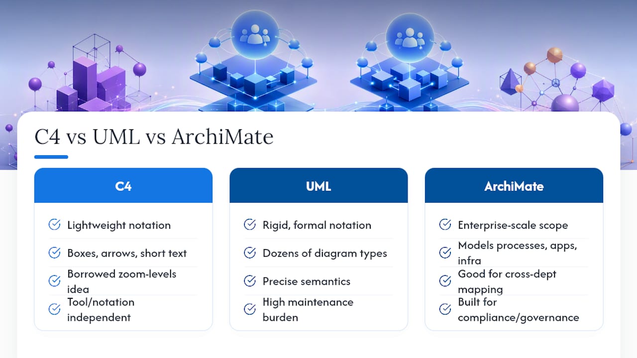
The honest tradeoff: UML and ArchiMate model more kinds of relationships and support formal governance requirements C4 was never designed for. If you need traceability across regulatory frameworks, C4 alone won’t cover it. If you need your engineering team to actually read and update the diagram in front of them, C4 usually wins.
How Do You Keep C4 Diagrams Accurate as Architecture Changes?
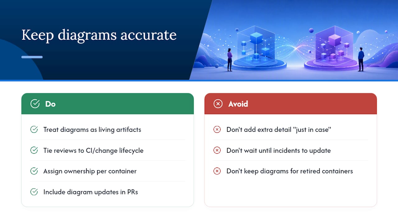
Architecture is never static, and a diagram that was accurate at launch is often wrong within a quarter. The teams that keep C4 diagrams useful treat them as living artifacts with an owner and a trigger for updates, not a one-time deliverable from a design sprint.
Set a lightweight review cadence tied to your actual change process. A practical approach ties diagram review to the CI or change lifecycle rather than a fixed monthly or quarterly check, since architecture changes cluster around releases and refactors, not the calendar.
Assign ownership per container. The team that owns a service should own the container-level box and any component diagram that exists for it. When ownership is unclear, diagrams tend to sit untouched until someone notices they’re wrong during an incident, which is the worst possible time to discover it.
Diff your diagrams the same way you diff code, if you’re using diagram-as-code tools like PlantUML. A pull request that changes a service’s dependencies should include the container diagram update in the same review, not as a follow-up ticket that never gets filed.
Finally, resist the urge to add detail “just in case.” A component diagram maintained for a container nobody touches anymore is worse than no diagram at all, because it actively misleads the next person who reads it. Delete diagrams for retired containers as aggressively as you’d delete dead code.
The tradeoff between precision and speed in agile teams
Teams often treat C4 as a compliance exercise, chasing full coverage across all four levels before shipping anything. That’s backwards. A context and container diagram that’s actually current beats a “complete” set that’s three sprints out of date. The rule worth adopting: a living, slightly imperfect diagram someone will actually open beats a polished one nobody trusts anymore.
Keep Your Architecture Docs as Current as Your Code
Segua turns the meeting where an architecture decision actually gets made into the documentation that captures it, instead of leaving that decision trapped in someone’s notes. Upload a recording or transcript, and the platform generates requirements, decision logs, and traceable artifacts you can attach directly to the container or component diagrams stored in your repository.
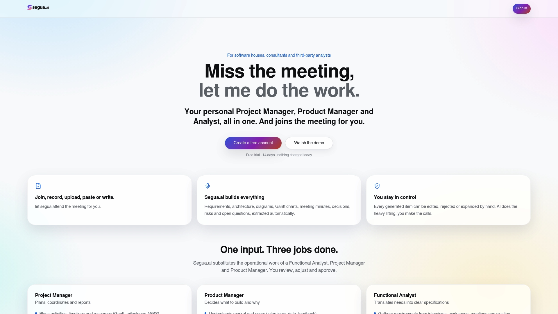
The workflow is straightforward: capture the meeting where a team debates a technology choice or a service boundary, let Segua generate the requirement or decision record from it, then link that record to the C4 diagram it affects. Segua also flags contradictions and unanswered questions across your project artifacts, so a decision that quietly reverses an earlier one doesn’t slip through unnoticed. Plans start with a free trial, and the Pro plan runs 39 EUR per month for teams ready to automate the documentation work that usually falls through the cracks between sprints.
Sources
- The C4 Model for visualising software architecture
- How to create software architecture diagrams using the C4 model
FAQ
What Is a C4 Style Diagram?
A C4 style diagram is one of four hierarchical, zoomable views (context, container, component, or code) that document software architecture using consistent, notation-independent boxes and arrows. Simon Brown created the model to keep architecture communication lightweight enough for agile teams to actually maintain.
What Is a C4 Context Diagram?
A C4 context diagram, the first and broadest level, shows your system as a single box surrounded by the users and external systems it interacts with, without any internal detail. It’s designed to be readable by both technical and non-technical stakeholders, which makes it the diagram most teams reach for first.
What Are C1, C2, C3, and C4 Diagrams?
C1 is the system context diagram, C2 is the container diagram, C3 is the component diagram, and C4 is the code diagram, each one zooming further into the system than the last. In practice, C1 and C2 cover what most development teams need day to day, while C3 and C4 get used selectively.
What Is the Best Tool for Creating C4 Diagram Models?
There’s no single best tool. Diagram-as-code options like PlantUML with the C4-PlantUML extension work well for teams that want version control and diffs, while GUI editors with C4 templates, such as Visual Paradigm, suit faster drafting or non-developer collaboration, and teams sometimes combine both approaches depending on the diagram level. A platform like Segua can help keep the decisions behind those diagrams documented and traceable as architecture changes.
Do I Need All Four Levels of the C4 Model?
No. System context and container diagrams are enough for most teams, and component or code diagrams should only get created when a specific container’s complexity genuinely justifies the extra maintenance burden.